
Home » New Lifts » New Lift Installations » Evacuation Control Lifts
| STANDARDS | BS9999 and BS9991 |
| DESCRIPTION | BS EN 81-70 Passenger lifts may be provided to be used by a designated person as part of a management strategy for evacuating people in the event of a fire. |
| FEATURES |
|
| LIFT SIZES | Minimum 8-Person 630KG Passenger Lift Type 2, although more common use is in larger capacity lifts used for the movement of disabled users, beds or stretchers. |
Please note: Images are representative only (hover over image to view item description)
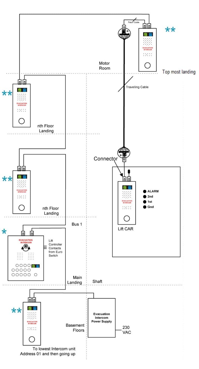
When the system is operated, a speech link will open to allow communication between the Main Control Panel * and any of the outstation speaker boxes ** in the system.
All calls will be registered on the Main Control Panel* when the “Call” button is pressed on any of the Outstations**.
To answer a call, the Evacuation Manager, simply presses the flashing button for the corresponding outstation. At this point a voice link will be opened. Once the conversation has finished, the pressing of the fully illuminated button, on the Main Control Panel*, will now cancel the call.
If for any reason the Evacuation Manager wishes to speak to an outstation, he simply presses the corresponding button of the outstation**. A voice link will be opened and the button will fully illuminate.
To activate the emergency lift evacuation system, place the EURO switch in the ON position. All the LEDs for the Landing Outstation Speaker Boxes and the Lift Car will flash for 5 seconds when the system is analysing the Outstations. After 5 seconds, the LEDs on the Main Control Panel will be ON for the outstations which are present working (i.e. Data Link is Working) for 3 seconds. The “Listen” Pictogram will be ON to indicate that the system is ready.
At the same time all Outstation Speaker Boxes Call Button will Flash slowly to indicate system is ON. On pressing the CALL button on any outstation, the LED will start flashing faster to indicate placement of a call. At the same time the corresponding LED for that outstation and a buzzer will operate. The flashing and buzzing will continue till the person on the Main Control Panel answers the call by pressing the corresponding button. At the point the voice link is opened, the LED on the calling outstation and main panel will remain ON till the voice link is terminated.
When Voice Link is active, press to speak button will control the speech from the master station. When press to speak button is released, Main Control Panel’s microphone will be muted and outstation microphone will be ON, and Main Control Panel’s microphone is muted. When press to speak button is pressed and Hold, Outstation microphone will be muted and Main Control Panel microphone will be ON. Pictograms at the Main Control Panel and the Outstation Speaker Box will show the status of speak/listen. i.e. when the speaker box’s Mic will be ON, “Speak” Pictogram will illuminate and when the Speaker Box’s Mic will be OFF, “Listen” Pictogram will illuminate.
A call can be made to any of the Outstation(s) by simply pressing the button for that Outstation on the Main Control Panel. As soon as the button is pressed the LED on both the Outstation and the Main Control Panel will be steady ON and a two-way communication is possible via press to speak button on the Main Control Panel.
The call can be terminated by the pressing the same button again at which point LEDs on the outstation and Main Control Panel will go off and the Pictograms at the Outstations will be switched off and at the Main Control Panel “Listen” Pictogram will illuminate to indicate the system status.
Acoustic feedback will occur when the Lift car doors open if the Main Control Panel is near the Lift car’s opening.
When Evacuation Switch is turned OFF, Both the Pictograms at the Main Control Panel will be switched off and Push Button LED at all the Landing Speakers will be turned OFF.

The London Plan 2021 is the spatial development plan for Greater London over the next 20-25 years. It discusses Emergency Evacuation Procedures, incorporating standards for fire safety of developments and robust strategy for building evacuation.
Under The London Plan 2021 Policy D5(B5), all new developments featuring a lift core must include at least one fully compliant evacuation lift per core.

Yes, please visit Breeam Compliance for further information.
Yes, please visit Hybrid Platform Lifts.
Yes, please visit our Accessibility Guide.
Yes, please visit Vandal Resistant Lifts.
Yes, please visit Firefighting Lifts.
We mostly provide 8-Person and 13-Person lifts but can accommodate from 4-P to 33-P, see more information about our lift shaft size requirements here.
Yes, please visit Open Protocol.
One of our team will contact you shortly.


